Model Mania @ SolidWorks World 2014 – San Diego
After a great week at SolidWorks World in San Diego, I’m now reflecting on how the technical content shown can impact positively our customers business, I hope to add a series of short blogs on a number of exciting developments
As an introduction I’d like to share with you my experience of winning the Reseller Model Mania Challenge at the conference and explain how I tackled the modelling challenge…
![]()
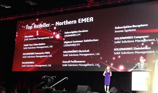
Here we have Mark Schneider part of the Product Marketing team introducing the winners of Model Mania and showing the rest of the conference on Day 3 the content of the challenge
MODEL MANIA 2014
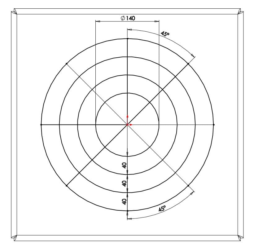
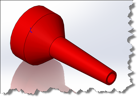
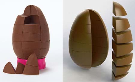
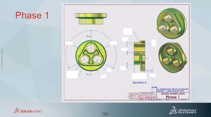
So to start the contest you enter a booth, close the curtains behind and sit at the laptop to review the drawing for a few minutes, then off you go…below you will see Phase 1,
![]()
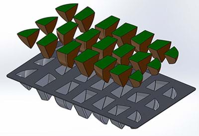
During the modelling process I aimed to keep in mind one of the most important aspects we teach in our SolidWorks Training Syllabus; that of Design Intent, as phase 2 required a design change (unknown at this point) I had to model the part keeping the feature tree flexible enough to accommodate the edits.
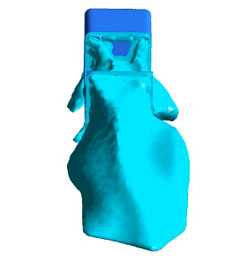
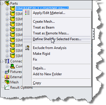
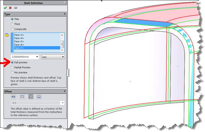
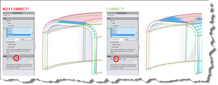
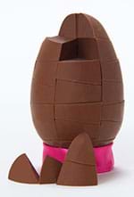
STEP 1: I first modelled the base with the fillets and shelled the body to its wall thickness
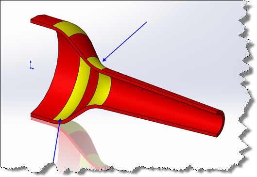
STEP 2: Next I modelled the triangular shape on the front using the circular cuts in the base as a reference with tangent lines to complete the sides, this was then trimmed using the useful Power Trim command
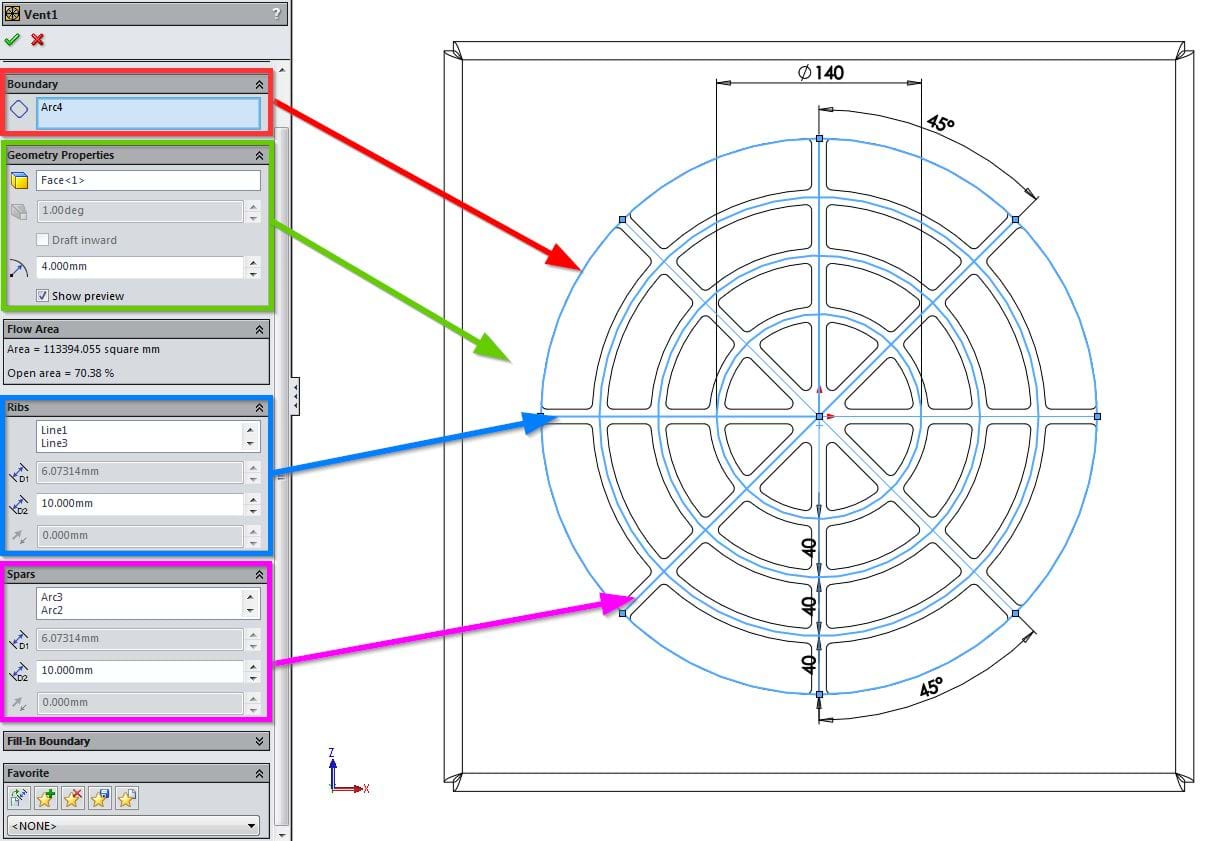
STEP 3: The circular cuts were then taken as a separate feature to allow for potential changes
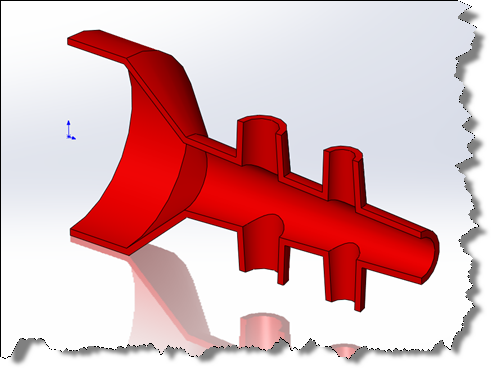
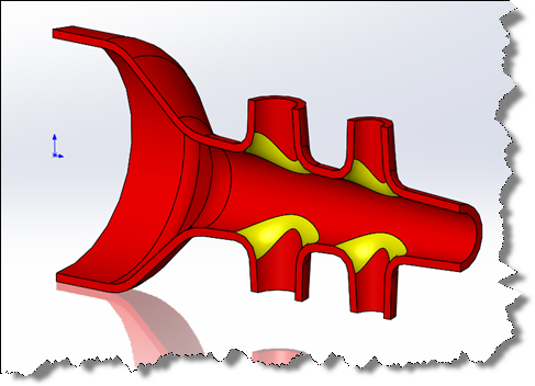
STEP 4: Using a series of offsets the ’Y’ shaped cut into the triangular feature was completed, cutting back to the base feature face
STEP5: The fillets were added and the correct material chosen
Although this maybe wasn’t the quickest modelling method, something I always stress in the training courses I teach is to keep the feature tree flexible for design changes and ensure the model is accurate.
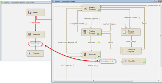
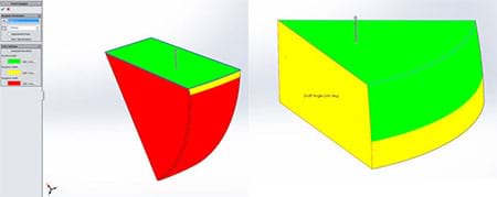
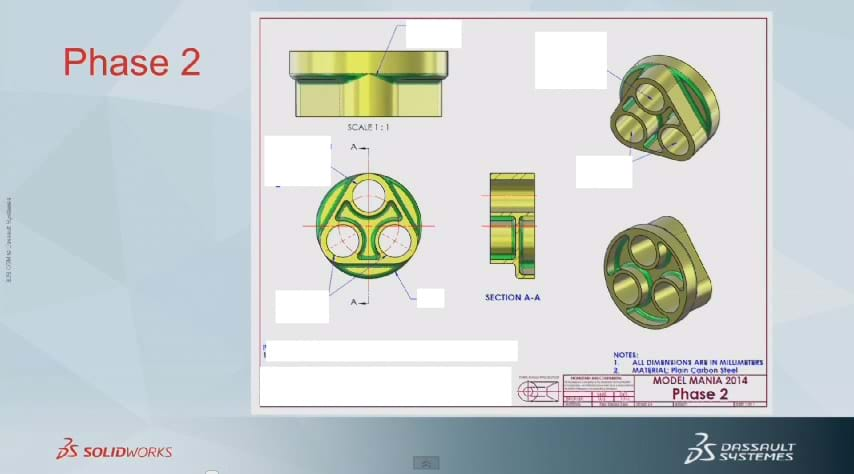
Once this was completed the SolidWorks Representative handed over the drawing for Phase 2,
![]()
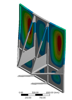
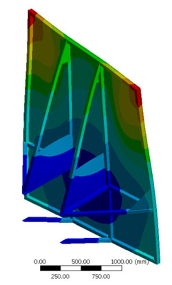
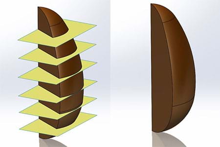
It indicated that the large diameter was to be reduced and that the fillet surfaces needed to be changed to aid manufacture. It also asked to run a simulation study to gauge the Factor of Safety of the component
This is then where my previous modelling methodology helped as I was able to independently change the base diameter without causing any feature errors, add the extra geometry and then re-evaluate the fillets and add the additional edge selections. The change therefore took less than a minute and I could move on to the simulation study. The easy setup tools of SolidWorks Simulation helped me create the study, run the results and evaluate the Factor of Safety in a couple of minutes
Model Complete!!
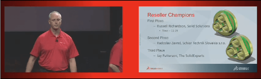
![]() So, back to Mark Schneider to announce the winners to the rest of the conference in the General Session Day 3, 5500+ attendees;
So, back to Mark Schneider to announce the winners to the rest of the conference in the General Session Day 3, 5500+ attendees;
A proud day!
By Russell Richardson
Elite Applications Engineer
.PNG)


.jpg)
.png)


.png)

 So, back to Mark Schneider to announce the winners to the rest of the conference in the General Session Day 3, 5500+ attendees;