Ever wondered how the big automotive companies create their impressive long exposure renders? Well wonder no more, with this webcast you will the see the vast and powerful range of features from SOLIDWORKS Visualise professional using options such as motion blur and depth of field.
↧
SOLIDWORKS Visualize - Motion Blur and Camera Options
↧
SOLIDWORKS Visualize 2016 SP1 Released
SOLIDWORKS Visualize 2016 SP1 Released
For 2016 SOLIDWORKS Visualize will have just a single service pack before it aligns fully with SOLIDWORKS 2017 Service Pack release schedule from October. Having just been released in February the development team have been hard at work adding improvements and fixes based on user feedback. You can view a full list of the fixes/ improvements and fixes here or from the help menu > Release Notes once installed.
Some highlights
- New option of importing “Camera” - currently this imports the angle/ camera angle the the SOLIDWORKS file was last saved in so not a true import of all camera properties/ multi cameras yet.
- Import check boxes are now remembered between sessions

- For Fast render mode you can now pick CPU, GPU or Hybrid render device

- Performance improvements when switching from Accurate to Preview mode and back.
- DPI value is now written into image file properties
- Various improvements for appearance and decal import*
- Fixes for duplicating configurations (versions/ colourways in Visualize Professional)
- * Only Decals with projection mapping are supported currently.
You can download Visualize 2016 SP1 from the SOLIDWORKS Customer Portal as below.

Scroll down to the bottom of the next page as below...

Once downloaded run the SWVizInstaller.Msi file to install, this will upgrade you to the latest release. The development team really have been hard at work and there is more to come for the Visualize 2017 release this October.
Alan Sweetenham
Elite Applications Engineer
↧
↧
SOLIDWORKS Visualize Why Go Pro? 3- Walkthroughs
SOLIDWORKS Visualize Why Go Pro? 3- Walkthroughs
The Walk-through function of Visualize Professional is a special type of animation where you simply move the camera and explore your design in 3D. You can control your travel using just your mouse or keyboard controls, move randomly along the floor, ground, or surface, fly around your design to get an aerial view and export the results to a video to share with others whether it be to your manager, client or for an exhibition.
Step 1: Prepare your files within SolidWorks. As with all models it is easier to apply simple materials to your bodies before taking it in to Visualize. At this point try to think what you actually want to show with this model. Delete any pointless bodies or geometry that are not needed or will not be seen.

Step 2: Import into Visualize. Often it is a good idea to untick environments as Visualize environments are often more advanced. Remember to select the appropriate ‘Part grouping’.

Step 3: Turn on ‘Use ALT + SHIFT for Walking Camera Navigation’. This can be found in Tools > Options > User Interface. This is what we are going to use to move around the model.

Step 4: Set your rendering quality to fast and apply your material appearances, scenes etc.

Step 5: Show the timeline by going View > Show timeline OR CNTL + L. Drag the red flag (showing the end of the animation) out to your desired time for your animation.

Step 6:
Go to your camera tab and copy a new camera by right clicking an existing camera, selecting Copy and then right clicking again in the camera tab and selecting paste. (It is always best to have more than more camera for Walk-through’s as one will be moving and the other can see where this camera is).

Position this camera where you want to start your walk-through. Set, from the camera tab with the new camera selected, an appropriate focal length (example 35 mm) and an appropriate height from floor (for example 1.8 meters for the average eye height).

Step 7: Make sure you’re at 0 seconds on the timeline (the yellow flag) and right click your new camera and add a key-frame.

Step 8: Ensure Auto Key-framing is turned on by making sure the stop watch icon is red. This way when you turn your camera in a new time frame a key will be added to the timeline automatically reflecting the new orientation.

Step 9: Move your timeline to a set increment (for example 2 seconds) by dragging the yellow flag. Next use SHIFT + ALT + LFT Mouse Button to move around to your next point of focus. This will add a key in to your timeline. Ensure the camera that you want has a red dot in the top left corner to ensure that a walk-through animation is being created.

Step 10: Apply the same process by moving to the next time scale and adding more views in by using SHIFT + ALT + LFT Mouse button. Remember to ensure your camera isn’t going up and down when it isn’t meant to be by ensuring your ‘Height from floor’ in the camera tab stays the same at each Key-frame.

Step 11: So you have now created your walk through but you want to view and edit your path? This can be done using the ‘ribbon’. To see this we need to change the rendering setting to ‘preview’ and change from your walk-through camera to a free camera (double click on the free camera).


In your timeline ensure the backwards S is coloured. If it is greyed out, simply left click on it to turn it on. You can either show all ribbons or hide ribbons or hide and show individual ribbons created using different cameras.

Step 12:

When you can see your ribbon you can use it to edit your path. Each key-frame has a box. If you select each box you can use the ‘move’ tools to bring up a triad. The red, green and blue arrows control where the box is and the white arrow and the rotating rings control where the camera is looking.


Step 13: Once happy with your walk-through you can then output a movie by going to the render tab at the top and choosing animation. When exporting animations there are two different tabs to go through, the ‘animation options’ and the ‘render options’. If you want to create a movie or your walkthrough, just make sure to select ‘create movie’ in the animation options tab.


You can see the other blogs in this series on Visualize Professional below;
Visualize Why Go Pro? 1-Configurations
Visualize Why Go Pro? 2-Render Queuing
Chris Green
Applications Engineer
↧
14 New Staff Join SSM Technical Team Today
Welcome to 14 new staff at SSM!!! The image shows our new crop of recruits who have joined our Technical team - 8 new Interns and 6 Graduates - with an awesome array of academic ability and SOLIDWORKS experience. They are a mixture of Mechanical, Aerospace and Medical Engineers and Product Designers. They will now start a 12 week induction and training programme and be based in Leamington Spa, Fareham, Leeds and Glasgow.
Welcome everyone!
![]()
![]()
By Andy Fulcher
Technical Manager
↧
Tech Support Blog: Why are my BOM Quantities Wrong?
A support call cropped up this week which I thought was worth sharing in a blog post. Quite simply a customer was reviewing their Assembly Bill of Materials (BOM) and finding an incorrect value for the Quantity column against a certain part. Clearly this column should simply sum up the number of identical components found in the assembly and report the value- so how can this go wrong?
The answer here is that you can, on a part by part basis, set the quantity to report a different custom property. Take for example accounting for paint, oil, grease or any other supplementary product that you want to show on a BOM. It would be unlikely you want a numerical value showing an item count up, but rather an amount on for example, a volumetric basis- so therefore it may be appropriate to show 10 litres of paint- hence need the flexibility to change what the quantity reports.
So in order to do this in SolidWorks, either deliberately or to correct a problem, you need to open the part (you can open parts directly from the BOM by right clicking the relative row). Then use File > Properties and change over to the Custom tab. You will see in the upper right corner a drop down menu titled "BOM Quantity"- this should ordinarily be set to "-None-" but can be altered to any other Custom Property found on that screen. So simply if the Quanity is wrong, set it to "-None-", if you want it to be a specific property, you can change this in the list.
Find our more about Bills of Materials in our Webcast archive
By Adam Hartles
Senior Applications Engineer
↧
↧
SOLIDWORKS Electrical portal & Gold Electrical Subscriptions
SOLIDWORKS Electrical Portal & Gold Electrical Subscriptions
The SOLIDWORKS Electrical portal is chock-full of useful content– including Manufacturers, books, projects, cables plus much much more! As you can see from the graphic below, it holds huge amounts of data from 565 manufacturers, over 7 million parts, 5 thousand symbols & nearly 7 million 2D footprints meaning there’s very little that you’ll need to create yourself.
This can be accessed from within SOLIDWORKS either the Manufacturer part library or the Help tab – Online Content.

When researching for my webcast a few weeks ago I noticed that I was unable to access the Gold Content within the Electrical Portal.

The Gold content is symbolised with a yellow/gold medal next to the download button for each manufacturer/project, when selected it may state that you don’t have the correct subscription package to access this content. BUT all SOLIDWORKS Electrical customers with an active subscription are entitled to this content.
What may not be common knowledge is that customers start with the silver package and if they would like to access the gold content they need to activate it. Open SOLIDWORKS Electrical navigate to Library> Manufacturer part Library. Then select ‘Update Subscription’ and enter the login details (these are the same as the details to the portal). It should say subscription updated once completed.

Gold content from the portal can now be accessed.
Olly Smith
Elite Applications Engineer.
↧
How to model the Olympic Sun Sculpture
How to Model the Olympic Sun Sculpture
The Olympics have started and we all saw the beautiful Olympic Sun Sculpture that formed the backdrop to the Olympic flame. It’s an elegant design and I immediately thought how easy it would be to model up in SOLIDWORKS. It’s all fairly standard features, the only tricky bit is mating up the assembly to give motion to this kinetic sculpture. So let’s get started!
Step 1: Draw The ‘Ring’ part. This gives the sculpture its basic size. Start by drawing a 30-sided polygon on the front face. I am not trying to make this full scale so I set the length of one of the edged to 250mm. To complete the part just turn this into a circular profile sweep. A great new feature that came in 2016. I set the diameter of the sweep to 70mm.

Step 2: Create a ‘star’ element. This is a little bit trickier, but still we can just use essential commands. I started with an Axis from the Front and Top planes. This Axis was then used to generate an angled plane 6 degrees from the front plane. Onto that plane I drew a Guide Sketch:

This ensures that I can get my star to fit nicely onto the ring.

WHY? Why did I make the angled plane? The answer comes later. Read on!
Step 3: Create the central bobbin section.

Sizes aren’t too critical here, just go with what you like.
Step 4: The Spoke. All sketches need to be on the new angled plane. The spoke first. Again I made use of the new Circular sweep to make this from a single line.
Just don’t make it too long. The Guide Sketch helps here. Next comes the Balls.

I tried to keep the spacing fairly even and also inside the guide. Finally we add the end disc.
I ensured that it didn’t go beyond the end of the guide curve, but that it was still a good size. This is more art than science, so go with what looks good.
Step 5: Rotate and configure. This part need 4 spokes, so a simple circular pattern is fine here. We also want to create versions of the part that is rotated in 6 degree increments. Once the circular pattern is in place, right click on the angled plane and choose Configure Feature. This brings up a table:

We want to create 15 configurations and set the angles for those in 6 degree increments. If only we could sort configurations numerically! (Those looking at 2017 Beta will see that this is coming! Happy days!) So why do this? Surely we could use mates in the assembly? Well, we could, but it is a little tricky and you end up having to create lots of mates. We will see how many I need using this method.
Step 6: Build the Assembly. Place the Ring part at the Origin. Add the First Star and mate the Right Planes to each other and make it concentric about the ring segment. (Remember you can use Sketch segments for this if necessary.)

Step 7: The first pattern Now we just need to pattern the stars to create half the finished part. Here we create an axis from the Right and Top planes. We need 15 at 12 degree increments.

Once in place, change the configurations of the instances so that they step through the angular steps.
Step 8: The final pattern To end the modelling, just do a final circular pattern, 2 instances equally spaced and there you have it:

What I really like about this is the elegant complex movement. So how many mates are in this complex kinetic sculpture? TWO!

Conclusion/Medal Ceremony
So there we have it the Olympic Sun Sculpture. Play around with the sizes and see what you can create. What if you had fewer spokes? More Stars? Let’s see if we can use Visualize Professional to create some stunning images of this iconic design. Now go and support your athletes as they follow the Olympic ideal and strive to make us proud and show how sport brings people together in these ever fractious times.
↧
Improving your carbon footprint with Sustainability
Discover SOLIDWORKS Sustainability in this video tutorial and see how you can use the software to improve your carbon footprint.

↧
Creating pub games in SOLIDWORKS
This webcast goes though how we can use SOLIDWORKS Motion to play pool!

↧
↧
SOLIDWORKS Simulation - Olympic Weightlifting
It’s always intriguing to witness the strength of Olympic athletes competing in sports such as weightlifting. But how often do we stop and consider the strength and safety of the Olympic equipment in use? Suspending hundreds of kilograms above your head is never a good idea if you’re not sure how well the equipment will hold up so let’s see how we can use SOLIDWORKS Simulation to help us understand how strong an Olympic spec barbell really is...
Loading Scenarios Tested:
- Static (World Record)
- Static (500kg and with remote load support)
SPECIFICATION:
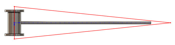
The first step was to model an Olympic bar alongside a set of standard weights according to Olympic/IWF specifications (weight designated by colour) using SOLIDWORKS. The extensive SOLIDWORKS materials library provided the properties for each component of the assembly. Utilising the Mass Properties and Measure tools allowed the volumetric dimensions of the parts to be modified to meet weight specifications.

Barbell: Stainless Steel [28mm diameter, 2m length, 20kg Total]
Barbell Ends: Chrome Steel [50mm diameter to fit weights]
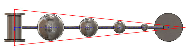
Weights: Rubber Coated Grey Cast Iron [50mm centre hole, 450mm diameter]
- Red 25 kg
- Blue 20 kg
- Green 10 kg
THE CURRENT RECORD:
The current Olympic record for weight lifted was approximately 263kg in Athens 2004 by the powerhouse Hossein Rezazadeh in the clean and jerk event. Modelling the complete lift would be better suited to aSOLIDWORKS Motion Analysis study. However, in this case in order to see the forces this would exert on the barbell using SOLIDWORKS Simulation we would use a snapshot of the lift at a key point at which the barbell would be fully suspended above the head.
SIMULATION:
A static simulation was conducted at first by rigidly fixing the bar at the centre, representing it as a loaded beam and applying a symmetry condition to model only considering one half of the bar. It was then possible to extract the resultant displacements alongside reaction forces under applied gravity.
Utilising the graphical output option in the probe tool, the distribution of stress at a selection of points around the centre of the bar could be identified. Maximum stress under these conditions was 461MPA (400 average) resulting in around a 5 cm deflection at the tips.
The stainless steel bar has a yield strength of around 513 MPa and from the first result the skin stress was approaching the plastic deformation region but to see the extent of this, the mesh sectioning or section clipping options could be used to see the stress through the cross section ensuring it stays below the max allowable stress.

Typical Olympic bars are rated to a maximum of 700kg before failure.

Applying 20 x 25 kg weights took the total weight of the barbell to over 500 kg at which point Herculean strength would be required to lift this above the average human head however the bar still managed to withstand the loads exerted as seen by the Stress plot. Deflections at the extreme ends of the bar were 80mm which would be quite evident when lifting. Repeated lifts of the bar would potentially result in the bar not returning to its original shape having plastically deformed but would be understood better through a fatigue study.
In SOLIDWORKS 2016 the ability to section meshes provides useful insight in to the stresses inside the bar through the cross sectional elements in 3D. This ensures that a fine enough mesh is being used to capture the behaviour inside a part or component and be refined if required. These options are found under the mesh quality entry or under the results context menu in the simulation tree. Using this tool, it is possible to analyse the barbell and clearly see the high tensile and compressive stresses at top and bottom (outer radial region) of the bar.

So far only rigid constraints from the centre were considered as it’s often difficult to accurately represent the changing constraints on the barbell when being lifted at any point during the clean and jerk (suspended above the head for example). One way to overcome this is through the use of remote loads to represent the forces and contact conditions indirectly exerted on the bar. For example, the reaction force of an athlete supporting the bar hence counteracting the weight force to some degree without applying additional contact constraints to the bar.

This ensured that the model would not be over constrained by rigidly fixing it in the areas where some movement would still occur (e.g. holding the bar at the grip handles). Why? Because over constraining meant a reduction in degrees of freedom at nodes along the bar that should otherwise be free to move. Doing so would me a reduction in how accurately the load was distributed through the entire span of the barbell and key information about how the barbell behaved when loaded would be lost in the simulation.
Assuming a super Olympian thrust the bar vertically upwards with an acceleration of 0.5 m/s^2 with a split second force of 5370N the barbell would still be able to withstand the load with around 520MPa max tensile stress and an 8cm deflection at the tips as seen by this simulation. Under these extreme conditions a safety factor plot could be used to explore the distribution of material strength with respect to the loading conditions. Whilst the outer surface of the barbell showed a high stress concentration, the rest of the bar was able to withstand the forces and remained in a safe region.


To summarise, we have seen how we can use a variety ofSOLIDWORKS tools with a simple static set of simulations to see if the performance of the barbell is up to par with the performance of Olympians. It’s safe to say that the next person to break the record doesn’t need to worry about breaking the bar, even if they manage to raise it…


Sameer Qureshi
Applications Engineer
↧
SOLIDWORKS Visualize Auto Animation
There are a few different animating tools within Visualize Professional but in this blog we will use the watch to illustrate the power of the automatic rotation animations, a method of doing quick and easy rotation animations with little effort. This can be great for things such as car wheels or in this instance, watch hands. In the following video you can see the hands moving round. This is done with just a couple of clicks but will make your designs pop and come to life.
[EMBED-VIDEO-1127]
Step 1:
To start any animation off you need to view the timeline. This can be found in View > Show timeline or CNTL + L as a shortcut.

Step 2:
Ensure your tree structure is suitable and you can select the parts you need with nothing you don’t want to be rotated being accidentally selected.

Step 3:
Find the parts you want to rotate (in this case I want to rotate my watch hands), and right click and select ‘Add rotation Animation’. This will add you rotation to the timeline under whatever you named your parts as plus ‘Rotation Animation’ so you may want to rename your parts before adding your animation.

Step 4:
If you select the keys you can simply input the start or end times for this rotation. If you select the coloured space in-between the keys the animation properties appear on the right hand side of the timeline where you can edit things such as ‘Total Rotation’ and the ‘Axis of rotation’ as well as Ease In and Ease out which means you can make your parts accelerate and decelerate.


NOTE: You can also add a rotation animation to cameras so if you wanted to rotate a selected camera around an axis by certain degrees it is easy to do so. All you need to do is right click on a camera in the camera tab and select ‘Add Rotation Animation’. This adds this rotation to your timeline and you can edit these in the same manner as the part animations.

By Chris Green
Applications Engineer
Models edited from:
• Kalle K - https://grabcad.com/library/f360-demo-watch-1
• Steen Winther - https://grabcad.com/library/eta-6497-1-complete-watch-movement
↧
SOLIDWORKS PCB – Templates & Libraries
One of the first tasks with the software is setup; this webcast reviews the creation and reuse of schematic templates, as well as the creation of schematic and PCB libraries within SOLIDWORKS PCB.

↧
Series 1 Land Rover Pedal Car - Made Easy with Solidworks!
The Series1 began production in 1948 designed to help get Britain farming after the war effort. It grew extremely popular and today enthusiasts are prepared to throw their life savings at restoring originals from that period.
The simplicity of the body shape made this the ideal choice for a pedal car home DIY project. This has been a low budget one-off manufacture and therefore many of the parts are recycled from surplus joinery materials. Solidworks 3D CAD tools have been utilised to take what may have been bonfire wood and turned it into something exciting.

Basic design specification:
- Ergonomically suited for a 2-3 year old child
- Traditional forward push pedal arms that link to a rear axle crank (to prevent feet being trapped)
- 4:1 steering ratio to give light steering and sufficient movement at the hand wheel
- Closely represents a scaled model of the Series 1
Appropriately sized, cheap, readily available wheels (regularly seen on heavy goods trolleys) were sourced and provided a starting reference. With the wheel diameter in mind, a sketch picture showing elevations is scaled and traced to give a profile ready for building features.

The chassis and body are both created as a single part file containing multiple solid bodies. This gives the advantage of modelling the overall shape in one environment.
A common misconception is that Solidworks Weldment functions apply specifically to steel structural members. However in this case we can regard the multibody wooden framework as a weldment structure from which we can produce a cut list. By applying bounding boxes, the resulting cut list properties contain length, width and thickness for each individual part of the structure.

When it comes to designing the steering linkage and drivetrain components it is incredibly useful to have full control within the assembly environment. Update the dimension of a referenced part and you can see the resulting behavior immediately, without the need to move away from your preferred view orientation. All instances of the modified part rebuild simultaneously.

Pictorial drawing views with coinciding Bills of Material are effortless to create either in a top or sub assembly level. This is a convenient way of communicating details, parts lists and assembly instructions for individual areas of the design.

Nice to see another Series 1 roll off the production line!


By Kyle Craig
Applications Engineer
↧
↧
SOLIDWORKS PCB – Effectively using Design Rules
A webcast reviewing the use of Design Rules within SOLIDWORKS PCB. If used correctly, you can save time by setting up the rules which then help drive the creation of your PCBs. These rules can also be exported out for reuse in other projects.

↧
The link between SOLIDWORKS Flow Simulation and SOLIDWORKS Simulation
Taking the data collected from SOLIDWORKS Flow Simulation we will process that into an FEA study to see what stresses can appear from the results obtained from the Flow Simulation.

↧
Earthquake analysis with SOLIDWORKS Dynamics
SOLIDWORKS Simulation (dynamics) can help us predict the effects from earthquakes, the resultant stresses and displacement ultimately show us whether the structure is fit for purpose. We will look at how to use the response spectrum analysis within a Linear Dynamic study and simulate an earthquake’s effects on a house.

↧
Home Improvements – the SOLIDWORKS user way (Part 1)
Ever thought about making those home improvements but didn’t want to employ that architect or interior designer, well why not use your SOLIDWORKS skills to get creative and visualise your ideas. Join us for Part 1 of 2 as we build a home from a set of plans and use configurations to try out different layouts and improvements.

↧
↧
Robot Wars – Design your own robot with SOLIDWORKS for the next series!
Robot wars returned this year to the BBC with great excitement and destruction. There

Among other things use sheet metal to create your shell and flatten to send them to the milling machine.

Use weldments to develop the frame and develop a cut list so you can make sure you cut your parts to the correct length and save on wastage.

Use motion studies to make sure those pesky flippers
[EMBED-VIDEO-1134]
Use simulation to analyse if your design will stand up to the inevitable beating.

And use Visualize to see what your design will look like.

All this without having to step into the workshop! Be sure to check out and enter your robot for the possible next series on www.robotwars.tv
By Chris Green
Applications Engineer / Robot Wars Fan
↧
Configuring a Revision Block in PDM
Since SOLIDWORKS PDM doesn’t support the automatic population of Revision Tables, customers often ask us how to populate a revision block in their SOLIDWORKS Drawing Borders when using PDM. Watch this Webcast to learn how to configure the Data Cards in PDM to drive the data into a Revision Block on your Drawing Border.
↧
Populating PDM Professional Card Lists from Excel
We are often asked if it is possible to populate a list on a data card from an excel spreadsheet rather than input this data manually. Watch this Webcast to learn how to set up data card lists to read from an excel spreadsheet regardless of whether this is stored inside or outside of the PDM Professional environment.
↧